compiled by Kevin Strom, WB4AIO
July 2024
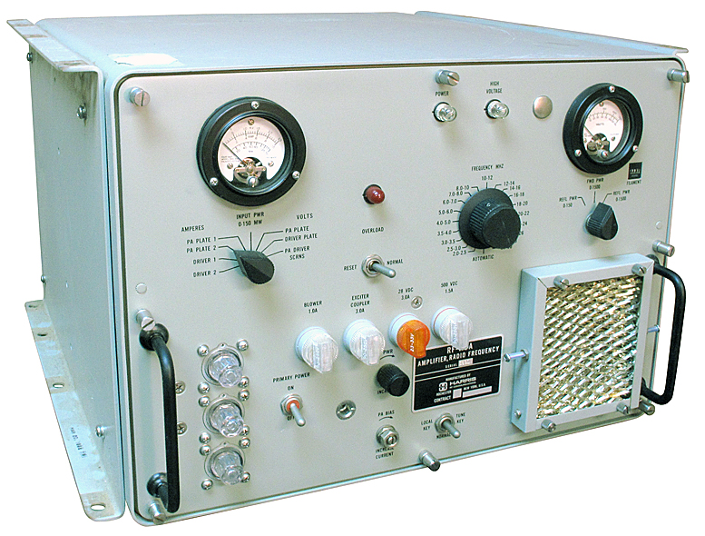
The Harris-Intertype Corporation, RF Communications Division (Rochester, New York), designed the RF-110A 2-30 Mhz amplifier in 1967-1968 and produced it from shortly after that date until the late 1980s. This is the communications division of the same Harris Corporation that manufactures broadcast transmitters. The RF-110A was part of the RF-130 communications system, many of which saw service well into the first decade of the 21st century. It saw military, government, and commercial use. A few lucky amateur radio operators have obtained these units in more recent years.
It is designed to amplify a 100 mW 2-30 MHz signal to 1 kW continuous or PEP (or 250 W carrier on AM). It is a two-stage design, with a pair of 8122 tetrodes (some early models used 4CX250Bs) in parallel as class A voltage amplifiers driving a pair of parallel 4CX1500B output tubes operating in class AB1 with no grid current. This amplifier has exceptionally low distortion and 40-47 dB of gain. It is so conservatively rated that it can withstand continuous operation, even at beyond-spec power levels of 1500 Watts output (375 W AM carrier) or more. You can literally key the amplifier and come back weeks later and it will still be on the air at full power. It will fold back its power and continue to operate even if the SWR rises to 4:1. There is no need to use a matched pair of final amplifier tubes because the screen supplies of the two tubes can be individually adjusted so the tube characteristics match closely.
The RF-110A uses 20 separate bandpass filter banks to cover 2 to 30 MHz and no manual tuning is required by the operator; all he needs to do is set the bandswitch and he is ready to transmit. There are no external tuning and loading controls. I am told that the 2.0-2.5 MHz band filters are easily retuned internally to allow coverage of the 1.8-2.0 MHz amateur band.
Below I have collected some articles and videos by others, photos, manuals, and pictures gleaned from the Web and archive.org. I am placing them here because such material has a tendency to disappear from the ’Net as the decades pass, and I want amateur radio operators to have easy access to these documents.
I intend to refurbish my RF-110A soon and get it on the air on AM and eSSB, using an Anan-10 at greatly reduced power as an exciter. I’ll eventually update this page with my results, and I’ll also continue to add more resources as I find them.
73,
Kevin, WB4AIO.
Manuals:
HARRIS RF-110A Amplifier
by N2BC
[Update from amfone: Biggest drawback is NOISE. I made up a remote control box and the amp lives in the next room.
Some info here:
http://home.stny.rr.com/n2bc/Harris_RF-110A.htm
There are some pointers to more info there too.
Edit: Forgot to mention…. That web page is long outdated. Since I put it up I have made a couple changes.
1) My TS-850 has been replaced with an ICOM 756 & I drive the amp with the ICOM @ 100W but through a 200W 30dB attenuator. This keeps the ICOM quite happy and provides plenty of drive for the amp.
2) I replaced the very noisy muffin fan with a bit less noisy external squirrel cage blower. The new blower is mounted on a rack panel below the RF deck box & it’s output is to the front & directed thru a horseshoe shaped duct up and back into the front of the RF-110. This kind of kills the ease of getting at things in the RF deck but the 11K RPM muffin fan was just intolerable.
If you have any questions, hollar!
73, Bill N2BC]
This page is a “Work in Process” I plan to document bugs I find, mods I make, and the end result integration into the station.
I had a very pleasant ‘discussion’ via eMail with Dave Russell, W2DMR. Dave worked on the RF-110 and has been a big help in getting mine on the air. Dave passed along this brief history:
Maybe a little history of the amplifier is in order, if you haven’t caught up with it. Originally this amplifier was designed for the US Navy and carried the designation of AM 3924 and was part of the URT 23 transmitter system. In the Navy version there were 2 different power supplies, an external 50/60 Hz 3 phase supply and a 400 Hz supply that could be installed inside the amplifier ( I believe the 50/60 Hz supply was designated PP 3916 ). There was also an exciter ( T 827 ) and an automatic antenna coupler for shipboard whip antennas. Design of all this stuff took place in 1967 through 1968, and the first production run was for 1200 systems. Towards the end of the design phase, a couple of the founders of the company were going to go on a DXpedition to some islands off the west coast of Mexico, and a couple of us thought it would be neat if we could build a single phase power supply for the amplifier. We did, and built several which were taken on the expedition along with the amplifiers and couplers. After we got into the production phase it was decided to build a commercial version, and it and the navy version became quite a good product line.

Overview
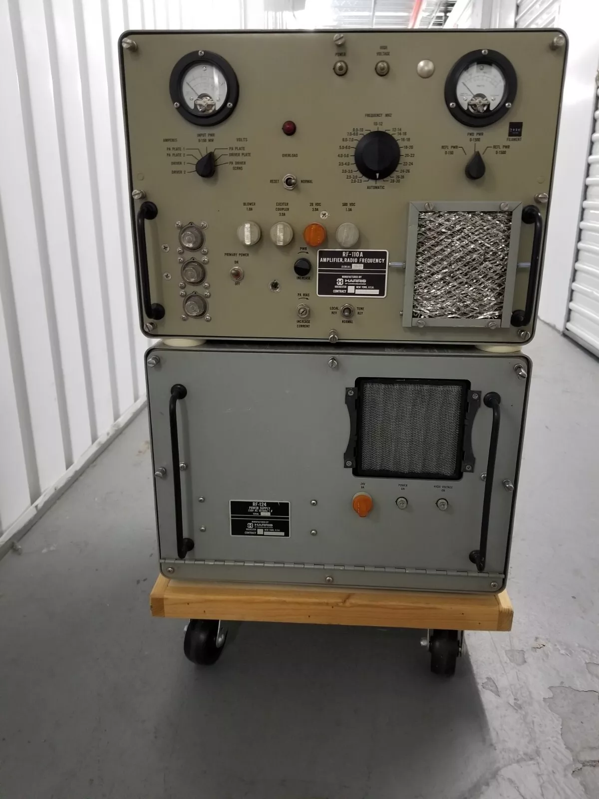
The RF-110A (top unit) covers 2 – 30 mHz in 19 segments. Input is 100mW to a pair of 8122 tetrodes running Class A. These drive a pair of 4CX1500B tetrodes. It is rated at 1000W output.
The grill area (lower right on the RF deck) is an air filter for the internal blower. The blower is a bit of a problem – it is LOUD. It is a rather small muffin fan spinning at 11,000 RPM. This will require some work to reduce the noise!
The RF-124 power supply (lower unit) is 230VAC single phase input and provides 2250VDC, 500VDC and 120VAC at 400Hz. The 400Hz AC runs the RF-110A blower and elapsed time meter. The power supply also has a muffin fan that starts with the application of HV. It is not nearly as loud as the RF-110A blower.
The RF-110A weighs around 80 pounds, the RF-124 is probably close to 200 pounds. Each unit is 12.5″ tall.
A version of the manual is available on K4XL’s BAMA archive thanks to YO9FZS.
Additional RF-110A information can be found at Kris Lund’s website, LX2KL.

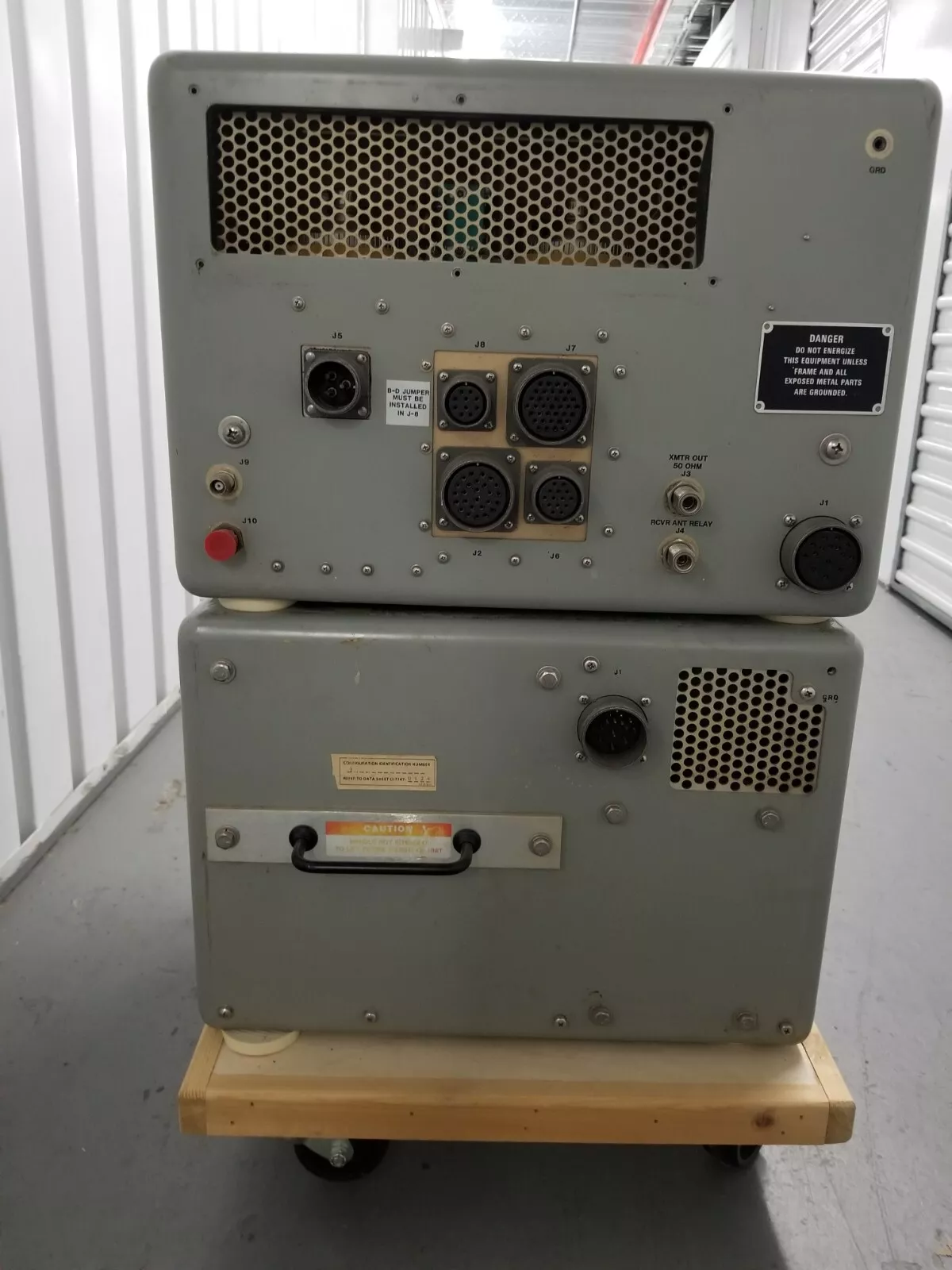
Rear View or the RF section. Shows the Mil-style connectors used. AC enters the RF-110A at the left-most circular connector. The lower-right connector is for a cable to the power supply.
The four connectors clustered in the center are for the Harris exciter, a “patch panel”, the Harris auto tuner, and a connector with some “accessory” lines.
About the connectors…. I had seen a post indicating that the William Perry Co. in Louisville, KY would be a potential source. I gave them a call (502-893-8724). What a pleasant experience! Not only were the connectors readily available, they were not all that expensive. And, Mr. Perry wanted to send them to make sure they would work BEFORE I paid for them.
Now, armed with the connectors, the cable between the RF-110A and RF-124 can be built. It contains the AC mains to the power supply, control signals, 500V and 2200V for the anodes and 115V 400cycle AC generated in the RF-124. I understand the cable is available from Harris – at something over $1K. You can build it for $20 worth of connectors and junque-box wire.


Left: Top view of the RF deck. Above: “the business end”, a pair of 4CX1500Bs.
The copper-colored area in the left picture is the PA tank assembly. The motor-driven bandswitch is in the center of this area.
The left side of the RF deck contains a VSWR bridge that feeds an internal ALC circuit. ALC and control / safety circuits are mounted on two plug-in cards.
Connecting it up
The Harris only needs 100 to 150mW of drive. One way to interface the Harris with typical 100W rigs is to remove the 8122 drivers, add a non-inductive load to the 4CX1500B grids and feed the finals directly with 20 watts or so.
I decided to use the Harris closer to it’s original implementation. I was worried about overdriving the control grids of the finals as they are only rated at 1W dissipation each. In addition, directly feeding the finals means disconnecting the internal ALC system that is in place to protect them!
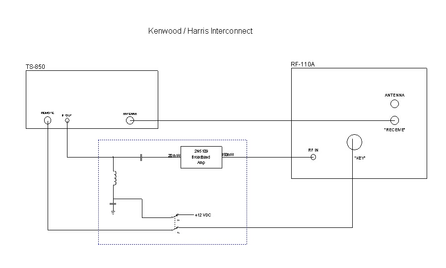
Most modern HF rigs have a provision to drive a VHF or UHF transverter. The Kenwood TS-850 puts out from 10 to 30mW depending on the band. The TS-850 requires a small change internally – well documented in the Kenwood manual – to enable the transverter output. The TS-850 user has to chose between a receive IF output or the transverter function as one connector is used for both. When the transverter is enabled internally, sending +12VDC into the IF OUT picks a relay which diverts the Kenwood transmit pre-driver from the PA to the IF OUT jack.
I built a small “control box” for the Harris and a simple one transistor broadband linear amplifier to pump up the 10mW to 150mW or so. A big THANKS! go to Zack Lau, W1VT – see QEX May 1992. A two-pole switch applies 12V to the Kenwood turning on the transverter output and completes the PTT path from the Kenwood to the Harris.
On receive, the coax relay internal to the Harris passes the signal to the Kenwood via the normal Kenwood UHF connector. For barefoot transmit operation (transverter off and amplifier keying disabled), 100W output from the Kenwood is connected to the antenna thru the Harris coax relay.
In ‘transverter mode’ the output level of the Kenwood can still be varied using either the POWER or CARRIER front panel controls. In addition, the internal ALC functions of the Harris control the bias and therefore gain of the 8122 driver stage to keep the PA happy. WORKS GREAT!
By the way, before I built the little 150mW amp stage, I drove the Harris with only the 20mW or so from the Kenwood. The Harris happily turned this into 1KW output, a whopping 47dB gain if I did my logarithms correctly.
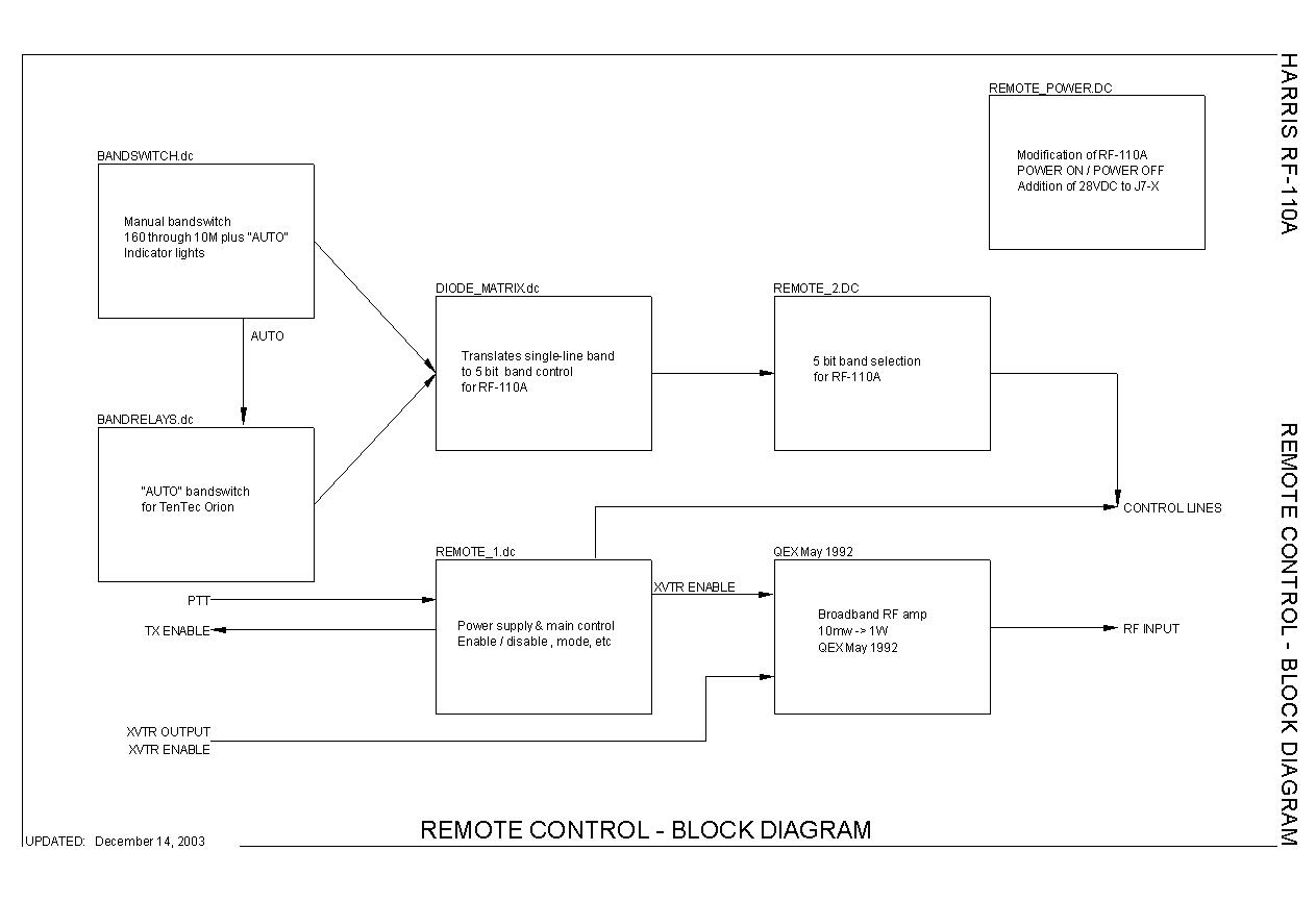
Remote Control
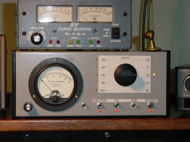
The control box I built contains the small RF booster amplifier, power and mode switching, remote bandswitch (more on that below), and a meter which displays the voltage from one of the Harris ALC circuits. I found that this is handy information to ensure I am not overdriving the amplifier.
Note that I included 60 meters on the bandswitch… I completed drilling the holes for the panel the DAY BEFORE the FCC announced the plan for 60 meters. Won’t be using that position!
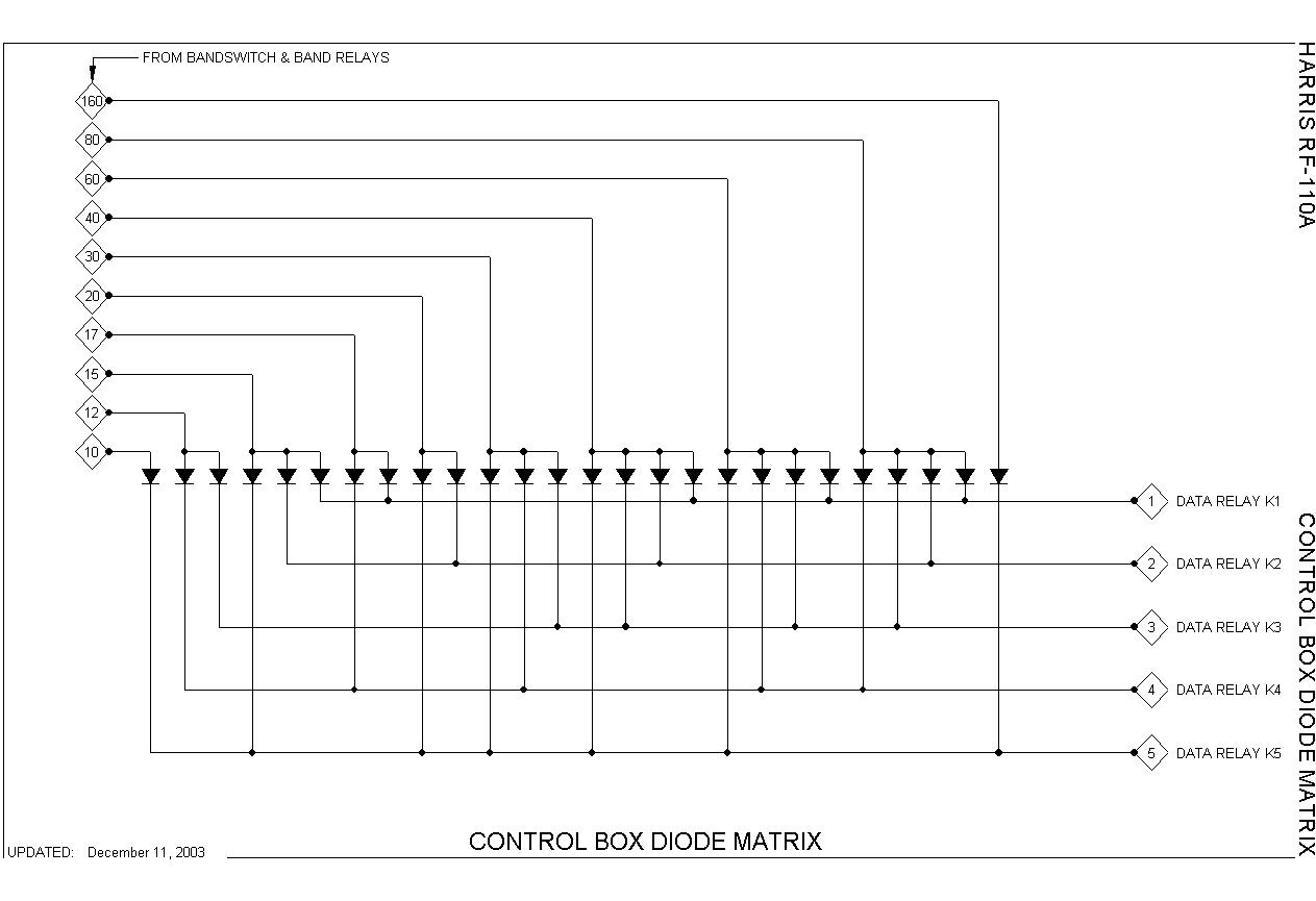
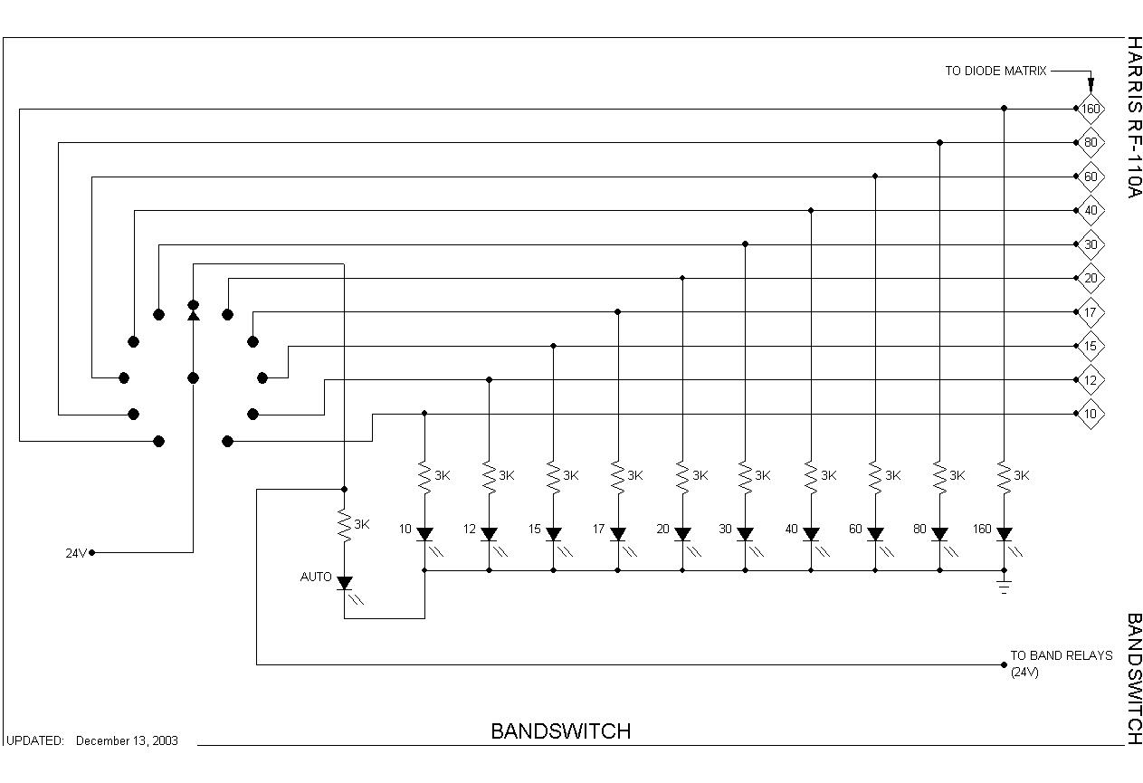
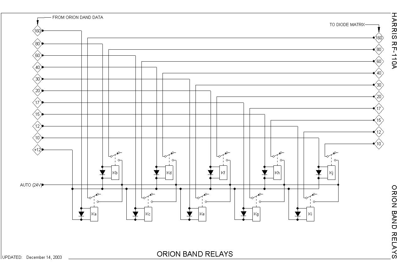
Remote Bandswitching
The bandswitch motor in the Harris can be remotely controlled through 5 data lines available on one of the interface plugs. My remote control box picks the appropriate relays determined by a diode matrix. The position marked “AUTO” will be used to interface band data from the transceiver to directly control the frequency range of the Harris.
JPG files of the remote control box schematic [following are 5 of 8 pics; three were missing from archive.org version of site]:
— 30 —
RF-110A Modifications
by Kris Lund
I’m Kris Lund, located in the beautiful Luxembourg’s Ardennes.
I was first licensed in 1967 as LA3OL. Later, in 1976, I moved to Luxembourg and got the callsign LX2KL.
Here you will find a lot about RF Amplifiers. Inrush current measurements and solutions are described on the Dentron MLA-2500B and Drake L-4B amps.
Harris RF-110A is described, and detailed modifications shown.
Don’t forget to visit my soft start site.
At KRISTRONIC.COM, you’ll discover an easy to use, information packed web site.
The RF-110A is a 2 – 30 MHz linear power amplifier, lazily producing a 1 KW output. It uses two Eimac tetrodes, 4CX1500B in parallel as finals, and two 8122 as drivers. So, it’s a lot of power here. RF power input is 100 mW nominal. The RF-110A can be operated continuously in any operating mode. Broadband techniques eliminate the need for tuning the amplifier. The RF-110A divides the 2 – 30 MHz frequency spectrum into 19 bands which are pretuned for optimum performance. The appropriate band can either be automatically selected by remote control, or manually selected by the front panel band switch.
The RF-110A was designed and manufactured by Harris Corporation. It was also manufactured by Target Corporation.
Weight: 43 kg (95 pounds).
| The RF-124 Power Supply is used to power the RF-110A. The primary input power can be wired for 208, 218, 230 or 242 VAC, single phase, 50/60Hz operation. Power consumption is 4500W maximum. It provides the following output voltages: | ||
| Modifications. | ||
| To operate the RF-110A with ham radio transceivers, a few modifications should be applied. All the modifications shown here, is done without adding any cables / wires between the Main Chassis and the Case Assembly. | ||
| The RF-110A was designed for 1KW (PEP or AVG) output continuously in any operating mode. It will run in amateur radio service at 1.5KW output with no problems. | ||
| The RF-110A is a great amp! It has a super clean signal and a high reliability. | ||
| Note that all the mods explained here is referred to my amp, SN 3400 range. This amp is a later model, I guess it was manufactured around 1983. Earlier models may use other reference designators, parts, and circuitry. |
| RF-110A Control: If a Harris exciter is used, the control of the RF-110A is obtained by the exciter. But if used with other exciter / transceivers, a control box can be used as shown in the manual. However, I decided to build all the control functions into the RF-110A. That consists of a 28VDC power supply, switches, LED’s, resistors and a RF input relay. See schematic below. | |
| The thermal Time Delay Relay 1A1K4 is a 3 minutes time delay relay. However, the resistor R21, 33 Ohm in its heater causing a time delay of 4 minutes. Note that the pins 1, 4, 6 and 7 are internally, electrically connected together. The LED X2 will illuminate after 4 minutes, indicating that the amp is ready for operation. First after these 4 minutes, and with the HV switched ON by S11, it’s possible to key / operate the amplifier. If the HV is not switched ON by S11, it’s not possible to key / operate the amplifier, and the amp is bypassed.For the 4CX1500B tubes, the Eimac technical data sheet recommends that the heater voltage should be applied for a period of not less than 3 minutes before other operating voltages are applied. From an initial cold condition, tube operation will stabilize after a period of approximately 5 minutes.Keying lines: The keying lines are connected to J7-K and capacitor C3 in the Filter Box 1A2A1. In the upper, left hand corner of the Filter Box is a hole, plugged with a cover. Remove this cover, put a rubber grommet in the hole, and let the two keying line wires pass through, going to the new RCA jacks, mounted at the rear panel, above the J3, RF Output connector. | |
| T-R switching: | |
| Using the RF-110A with a ham radio transceiver raises a few matters of concern. | |
| | |
| Some possible solutions: | |
| Add a relay at the RF input, so that the amplifier is bypassed when not keyed. See schematic above. | |
| Install high speed vacuum relays. | |
| The advantage using high speed T-R switching when used with modern, fast switching QSK rated transceivers is to avoid hot-switching. The relay-contacts should have no signal voltage applied, when they are opening or closing. Switching with voltage on the contacts, (hot-switching), will cause the contacts to arc. To accomplish this, vacuum relays are the preferred solution. In any case, the relays must be wired so that the amplifier can only can be keyed / operated when HV is On. See schematic above. | |
| The new RF input relay K2 wiring, see schematic above. It is mounted near the RF output relay K1. I used a TOHTSU coaxial relay, Model CX-600N-24. | |
| For RF input and RF output relay contacts wiring, see the RF Drive/Match page. | |
| The RF output relay K1 (antenna relay) is rated to 1 KW peak, single tone, and max. 500 MHz. Rated switching time is 15ms. | |
| The coaxial cable used at the output, is the RG-142B/U, having PTFE Teflon dielectric. Most manufacturers technical specifications says max. operating voltage of 1900 VRMS. This cable will handle well over 2000 Watts at 30 MHz, as should the BNC’s as they all have PTFE Teflon dielectric. | |
| Note that high ambient temperature and high altitude reduces the power rating by impeding heat transfer out of the cable. And high VSWR reduces the power rating by causing heat in the cable. | |
RF Drive & match:
The RF drive of this amp is 100 mW nominal. This is not that convenient for use with ham radio transceivers. The best way is to remove the two driver tubes and its circuitry, and install a non-inductive 50 Ohm load resistor at the RF input of the final tubes, near the tubes sockets. But now the input VSWR will be very high at frequencies above approximately 10 Mhz.. The reason is that the load is capacitive. The grid input capacitance of the two 4CX1500B tubes is about 160 pF. (One tube has 80 pF). To achieve broadband matching, a compensation network (low-pass filter) can be installed, see schematic below.
RF-110A input matching
Below is the measured RF input V.S.W.R.
Freq. Mhz 2 3.7 7 14 18 24 28 29 30
V.S.W.R. 1 : 1.0 1 : 1.0 1 : 1.0 1 : 1.2 1 : 1.0 1 : 1.2 1 : 2.0 1 : 2.0 1 : 2.0
Also on the schematic, the added input relay is shown.
CAUTION
Rotating the Driver or the Final Transformer bandswitch wiper backwards will damage it.
NOTE
The Driver Transformer Assembly must be installed! Its rotary switch deck, close to its front , S1C, Front and Rear, is the Decoder Master and Decoder Image rotary switches, which are connected via TB1 to the front panel Bandswitch S7, (and external bandswitching).
When the front panel bandswitch is turned to a new frequency band, a ground will be supplied, going to the Driver Assy Decoder Decks and, through the wire on TB1-6 to the motor, which will then rotate. When the Decoder Decks on the Driver Assy arrives to the same band position as the front panel bandswitch, the decoder decks on Driver Assy will open that grounded line, and motor stops. On the top of the Final Transformer Assy, the arrow shall be between the two lines of the band selected.
If you want to remove the Driver coils, simply cut the coils with a side cutter, and remove them.
DO NOT loosen / remove the nut on the rotary switch axis, nor the front and rear metal panel. If you do, most probably an alignment of the indexing between the Final Transformer switches and Decoder switches must be done.
NOTE
The front panel Band Switch can be rotated in any direction. The motor will only rotate in one direction.
Some details about the modification:
Driver Tube Assembly 1A1A1:
I removed the two driver tubes, and all other components and wires. Also the metal bracket where these components were mounted on was removed. So only left from this assy, is the cover plate, where the holes were closed with screws.
The metal bracket, mounted on the side wall was also removed.
Driver Transformer Assembly 1A1A4:
On the left, the rear plate of the 1A1A4 Driver Transformer Assembly is shown. To get more space for the RF input circuitry, part of the plate is cut and removed as shown.
All coils and resistors, and RF Input and RF Output contact plates were removed.
Caution! See note above.
Note that early produced 1A1A4 Driver Transformer Assemblies may look somewhat different.
RF Input Circuit:
The non-inductive 50 Ohm load resistor used, is from Palstar Inc., at http://www.palstarinc.com
It’s used in their DL300 Dummy Load. But you can buy the resistor separately from them.
I mounted the resistor on a rectangular piece of teflon, using two clips.
The two inductors are normal commercially available inductors.
Cooling
The RF-110A use a 115VAC, 400Hz, 11000 RPM fan. It deliver 140 CFM of air. This fan is very noisy, so I tried out some other solutions.
Note that my amp has the Driver Tube Assembly 1A1A1 removed, so only left from this assy, is the cover plate. The metal bracket, mounted on the side wall was also removed.
Also the 1A1A4 Driver Transformer Assembly was modified, by cutting off and remove a part of the rear plate. Plus all coils, resistors, RF Input and RF Output contact plates were removed. This causes less air flow obstruction, and maximum airflow to the final tubes.
So cooling is now required for the two final tubes only, plus some airflow through the Final Transformer Assembly 1A1A2.
The Eimac technical data sheet says that one 4CX1500B with Plate Dissipation of 1500W, require an air flow of 34 CFM. By 1000W plate dissipation, 18 CFM.
The maximum surface temperature rating for the anode core and ceramic/metal seals is 250 ° C.
I decided to try out some of the very fine blowers from EBM. On these blowers, the external rotor motor integrated in the impeller is mounted directly to the side wall inside the scroll housing. This unique integration of both rotating parts, the motor and the impeller, permits precision balancing. Both the motor and the impeller are directly in the air stream and are thus very efficiently cooled, resulting in minimum thermal and mechanical stress on the bearings which extends life expectancy. The housing is made of aluminum die-cast alloy.
An EBM G2E085-AA01-01 blower was installed, as seen on the picture. This blower is connected to 230VAC, 50Hz. It gives 47.5 CFM (80m3/h).
However, the air flow is marginal. Ok for lower RF output only. The solutions shown below are recommended.
Now an EBM G2E108-AA01-50 blower was installed. It is connected to 230VAC. The specifications are: 220 – 240VAC, 50/60Hz, 0.18A, 45W, 1700 RPM. It deliver 108 CFM (155m3/h). This blower is from RS Components, PN 223-089, where the 1.5µF / 400V capacitor is already mounted on the housing.
Motor type: Single-phase Permanent Split Capacitor Motor.
If ordered direct from EBM, the PN is: EBM G2E108-AA01-01. The capacitor is then separate.
The Dust Filter Assembly installed, is RS Components, PN 581-307.
An excellent, low noise blower.
Here another solution. The blower is positioned away from the amp, and connected with a flexible air hose fitted at the air intake of the amp.
The Blower activated air vane interlock switch.
If the blower fails to deliver the required air flow, this air vane switch is actuated (opens), and the overload circuit will trip.
The air vane switch will not activate (close) with the above blowers as the air flow is lower than the original fan. This can be solved by increasing the sensitivity of the switch. I’ll come back to that.
Another solution is to bypass the air vane switch by shorting the two wires on the switch together, but then the air flow is not monitored anymore.
To be continued…
Protection
| Here a summary of the protection circuitry in the RF-110A. For more detailed description, see instruction manual. |
| Overload and Sampling Circuitry |
| This circuit constantly monitors:- the final amplifier tube 1A1V1 cathode current- the final amplifier tube 1A1V2 cathode current- the RF output voltage from the final amplifier- the temperature of the RF-124 Power Supply. If any of these signals are abnormal, the overload circuit trips, unkeying the RF-110A, energizing an overload indicator in the amp, muting the transmitter and prevent further operation until the fault is cleared. The overload circuit can be reset with the front panel NORMAL / RESET switch. Also, if any of the interlock switches or the air vane switch is actuated (open), the overload circuit will trip. |
| Zener Diode Protector Assembly 1A1A9The purpose of this circuit is to protect the screen zener diode string 1A1CR7 through CR11.An arc from the plate to screen of either 1A1V1 or 1A1V2 final tubes will clamp the final amplifier tube screens to ground by firing the SCR, 1A1A9Q1, which causes an alternate shunt current path from the tubes screens through the diodes 1A1A9CR2 and CR3 to ground. The SCR, 1A1A9Q1, fires within 1µs. |
| APC (Average Power Control) and PPC (Peak Power Control)These controls prevent overdriving of the amp and also to keep the average talk power high during SSB operation.The PPC is a fast time constant, peak detection type circuit which senses the output RF envelope.The APC is a longer time constant, averaging circuit that delivers a positive going output proportional to average output RF level.These control voltages are fed back to the exciter to control its RF power output, which provides a constant predetermined output level from the RF-110A.Also, the VSWR Bridge reflected power output is monitored. If the VSWR, and therefore the reflected power, increases to about 360 Watts (4:1 VSWR at 1 KW forward power) and above, the APC-PPC circuit will generate an increasing control voltage output to reduce the RF output power from the exciter and therefore also the RF-110A RF output power. Therefore, the amp is protected against over-dissipation that would result from excessive VSWR on the transmission line.The APC and PPC will only function if their control voltages are fed back to the exciter used.Both controls, are adjustable and adjusted to suit the exciter used. It is adjusted by R12 APC ADJUST and R11 PPC ADJUST.Additional protection from overdriving is provided by the RF-110A Internal PPC loop. This loop will limit the output power by returning a control voltage (bias) to the driver amplifier in the RF-110A.Now, if the driver amplifier is removed, the Internal PPC loop of course does not function, neither the Power Control potentiometer on the front panel. |
Fixes and Increased HV
| 1A1A5 DC Power Control PWB. The Operate Relay Driver (for High Voltage Relay), A5Q7 transistor, 2N3019S, was found shorted. I replaced it with a 2N3421, with a small heatsink mounted on it. In early produced models (around 1974), the 2N2219A was used. |
| RF Bypass Capacitors, 1A1C2 & C3. These capacitors are rated to 3000V, so if you really want increase the high voltage, these capacitors have to be replaced with higher voltage rating types, otherwise you should experience an explosion!!! |
–30 —
E-HAM Reviews
| W5DTWRating: |
| W5XERating: I had the use of the RF-110 amp with the Harris 270-5 system which used the RF530 receiver and the solidstate transceiver to drive the 110’s. Had 3 of them in operation. 1 of the amps had the 8122 drivers, the other two had the 4cx250b but all performed excellently. They will run at the designed 1kw pep output level for day after day, week after week for months or years. Expensive if one has to replace the tubes but they were primarily in government service so the replacement costs not a factor. I might add that the RF110/124 system was also a part of the RF-131 system of which that exciter did all modes including ISB. Ray, W5XE |
— 30 —
fourierbwo
fourierbwo
K6YIC & N3FAA
K6YIC & N3FAA
K6YIC & N3FAA